How to use MEW-01 energy monitor readings to control other Supla devices?
Remote control of Supla devices using readings from the MEW-01 energy monitor. Simple automation built with SUPLA Scripts, step by step.
I work at ZAMEL. The devices described on this blog were provided to me by the company. All opinions and assessments are mine alone - the company had no influence on the content of the published articles.
Edit: 13.08.2025: This post is out of date. Supla now lets you create reactions.The MEW-01 electricity monitor is a device that we mount in the electrical switchboard. It can measure grid parameters such as frequency, voltage, current and power. Each of these parameters can be read through the REST API, and then used for example to control devices.
Today I want to show you how you can easily control other Supla devices using one of the measured parameters. In this example the parameter will be voltage. Of course there is nothing stopping you from using a different one.
To control things with our MEW-01 we will use SUPLA Scripts - an app developed by a person going by the nickname “fracz”, which adds new features to Supla, such as scenes, notifications or charts. Some of these features are of course available natively, but once you log in to a SUPLA Scripts account you will see the difference.
Let us go back to the introduction. Today I will show you how to read the grid voltage measured by the MEW-01, and then how to use that information to control other Supla devices. In my example I will use the ROW-04m device (a 4-channel modular receiver). Of course this will be only a simple example, to show the principle itself. Let us get to work.
Remember that this feature only works when you have Internet access. Do not use it if you do not know how to protect other devices in case it works incorrectly or loses the connection to the Internet. The feature may start a device that should not be running at that moment, or fail to switch it off.
1. We log in to our SUPLA Scripts account, and once connected we add the first scene in the Scenes tab. Our first scene will check the voltage measured by the MEW-01 device on phase 1. The basic assumptions for running the scene:
-
the measured voltage on phase 1 is above 250 V;
-
the output (channel) of the controller we are switching is off
If both conditions are met, the scene runs.
2. We move on to adding the first scene. After choosing the Scenes tab we press the Add scene button in the new window.
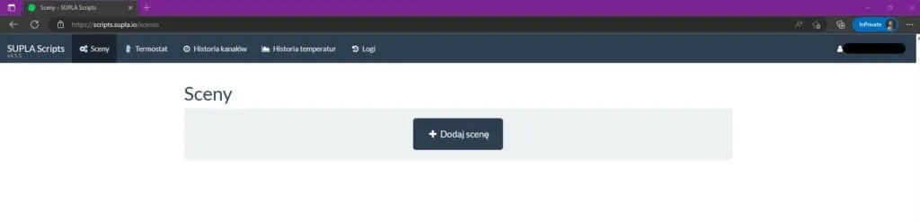
Scenes - Supla Scripts
A form will appear, in which we fill in the fields with the following example values:
Name: VOLTAGE > 250V
Run the scene from an action trigger in SUPLA: none
Scene trigger based on time: none
Scene trigger based on channel state: {{ state(MEW-01 MEASUREMENT CHANNEL ID).phases[0].voltage > 250 }}
Comment: phases[0] means the first phase, the next ones are phases[1], phases[2]. Voltage is the measured parameter. We can also use for example frequency, current, powerActive, powerReactive, powerApparent, powerFactor, phaseAngle, totalForwardActiveEnergy, totalReverseActiveEnergy, totalForwardReactiveEnergy, totalReverseReactiveEnergy
Condition for running the scene: {{ state(MEW-01 MEASUREMENT CHANNEL ID).phases[0].voltage > 250 and (not state(ROW-04m RECEIVER CHANNEL ID, THE ONE WE CONTROL).on) }}
Comment: the condition above checks whether the voltage is above 250 V and whether the receiver channel is off.
Actions: I pick the receiver I want to run the TURN ON action on
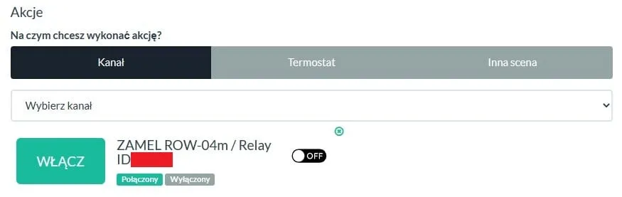
Running an action on a receiver channel in Supla Scripts
I leave the remaining options at their defaults:
Voice commands: none
Response: none
Pushover notifications: none
Scene available under a public URL (this option does not have to be checked)
Scene enabled
A correctly configured scene looks like this:
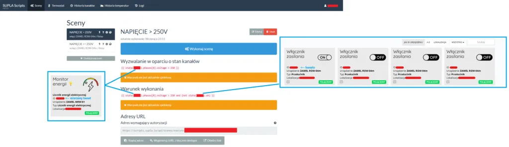
Voltage above 250 V - a scene for the MEW-01 in Supla Scripts
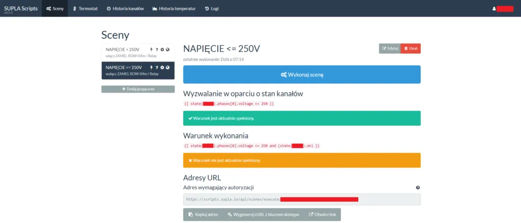
3. I move on to creating another scene, this time I will check the following condition:
- the measured voltage on phase 1 is equal to or below 250 V;
- the output (channel) of the controller we are switching is on
Name: VOLTAGE <= 250V
Run the scene from an action trigger in SUPLA: none
Scene trigger based on time: none
Scene trigger based on channel state: {{ state(MEW-01 MEASUREMENT CHANNEL ID).phases[0].voltage <= 250 }}
Condition for running the scene: {{ state(MEW-01 MEASUREMENT CHANNEL ID).phases[0].voltage <= 250 and (state(ROW-04m RECEIVER CHANNEL ID).on) }}
Actions: I pick the receiver I want to run the TURN OFF action on
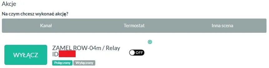
Running an action on a receiver channel in Supla Scripts
I leave the remaining options at their defaults:
Voice commands: none
Response: none
Pushover notifications: none
Scene available under a public URL (this option does not have to be checked)
Scene enabled
A correctly configured scene looks more or less like this:
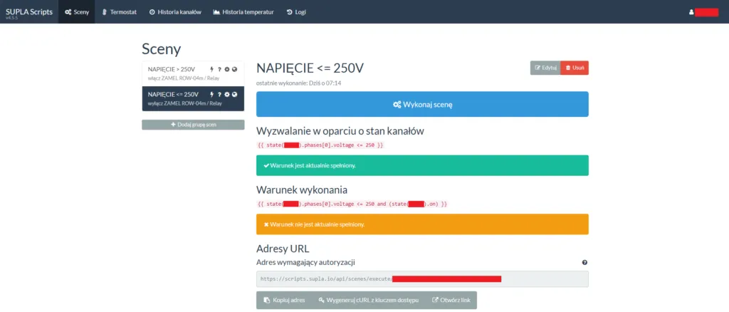
Voltage below 250 V - a scene for the MEW-01 in Supla Scripts
From now on, when the right conditions are met, the given scene will run and the MEW-01 energy monitor will control another Supla device. I encourage you to test this feature. If you have any comments or suggestions, write to me. Thanks!
If you would rather set this up together with me, book an online Supla setup session. You share your screen and I guide you step by step. Sessions are in Polish.
Try my online measurement analyser as well. It loads a CSV file with the measurement history of an energy monitor (MEW-01/MEW-02 from Supla Cloud) and immediately shows consumption over the ranges you pick, the hourly profile and a comparison of the G11/G12 tariffs - everything is calculated locally in your browser, without sending any data. It is a beta version, so give it a try: Energy monitor measurement analyser.
New posts also go out over RSS — no email address needed. Subscribe via RSS